Sentinels Manual

Hello, you soon to be Sentinel!

Why Sentinels you maybe wonder…?

Your tools are:
    • Soldering iron and solder
    • Soldering tip cleaning wire
    • Cutter pliers and Long nose pliers
    • Desoldering wire or pump
Your list of electronic components together with a soldering map is in your box.
Do you know how to solder?

Heat up the connection between the el. component and the circuit board, add solder and wait a few seconds. The perfect joint looks like a shiny volcano. 

1. Gently brush the circuit board with the sand paper

Copper exposed to air will oxidize [become green, black, blue], therefore gently brush the circuit with circle movements to remove the oxidized layer and soldering will be much easier. 

In the box you can find a small piece of sand paper. 

Tip: If I were you I would brush just the circuit and leave this beautiful colors. 

2. Solder the chips [IC]
    • Hold the legs on one side of the chip with Long nose pliers
    • Bend the legs of each chip for 90 degrees
    • Define which chip is IC1 and IC2 [each chip is marked with numbers and letters, e.g. 4046, 4069]
    • Place the chip on the circuit board and make sure the orientation is correct 
    • Solder first the upper right pin, then lower left pin

Note: Position of the chip is  important. The moon (notch / circle) on one side of the chip marks pin one. Search for similar indication (moon) on the circuit board.

3. Solder the resistors [R]
    • The color bands [4 or 5] on each resistor give you the information about the resistance value. Define the resistance via Resistor Calculator, multimeter or follow my cheat sheet below:
        • R1 = 1M Ohm [colors: brown, black, green, gold]
        • R2, R4 = 100K Ohm [colors: brown, black, yellow, gold]
        • R3 =  220 Ohm [colors: red, red, brown, gold]
        • R5 = 47 Ohm [colors: yellow, violet, black, gold]
    • Bend the legs to form a bridge
    • Hold the component with Long nose pliers above the resistor’s position on the circuit board, clip the legs with Cutter pliers and solder 
4. Solder the ceramic capacitors [C1, C2]

Follow the same procedure as for the resistors and solder the ceramic capacitors on the circuit board.  

5. Solder the electrolyte capacitors [C3, C4]

Follow the same procedure as for the resistors and ceramic capacitors, and solder the electrolyte capacitors on the circuit board. Make sure the orientation is correct! 

The size of the capacitor is printed on it (1 uF and 220 uF). 

Orientation of the electrolyte capacitors is important. The longer leg indicates the plus, the shorter leg indicates the minus. The grey lane on the capacitor’s body indicates the negative side as well.

6. Solder the light [LED]

Follow the same procedure as for the resistors and capacitors, and solder the LED light on the heart on the circuit board. Make sure the orientation is correct! 

Note: Orientation of the LED light is important. The longer leg indicates the plus, the shorter leg indicates the minus.

Fire fly – Solder the LED light on the booty! The LED light is already placed there. Use the longer wires from your box: 

    • Peal app. 3 mm on each side of the two wires and twist each side to prevent strands 
    • One side solder to the LED light and the other side through the two holes on the circuit board. 
7. Eat a cookie!

Take a break, open the windows. Did you know the Mountain Apollo is one the most endangered butterflies? Or that some fire flies are vampires? They seduce other fire flies by blinking aka communicating the same way in order to attract them and kill them? Or that bumble bees have a special way of pollinating? It is called buzz pollination. They sit on a flower,  hold it with the legs and they start flapping with the wings and shaking the body with it. This way the pollen flies around them covering their bodies. Bumblebees often fly in air temperatures as low as 10C or lower, because they can raise their temperature for flight by simply uncouple their wing muscles so that the wings themselves do not move, and use the muscles to shiver and raise their thorax temperature. Or that Jersey Tiger is sort of a moth who can not decide whether to be a moth or a butterfly, he flies during the night and during the day. 

Let’s continue…

8. Solder the audio jack [J]
    • Audio jack is placed on the back side of the circuit board
    • Peal app. 3 mm on each side of the black and red wire, which you can find in the box, and twist it to prevent strands 
    • Place the black [left side – negative] and red [right side – positive] wire through the hole of each leg of the audio jack and solder
    • Place the other side of the wires through the holes of the circuit board

Note: Wires should not stick out on the top of the circuit board too much.

9. Solder the power jack [PJ]

Solder the power jack from the bottom side of the circuit board.  Make sure the orientation is correct!

10.  Solder the potenciometers [P]
    • Potenciometers are placed on the back side of the circuit board
    • Peal app. 3 mm on each side of the black and red wire, which you can find in the box, and twist it to prevent strands 
    • Place the wires through the hole of each leg of the potenciometer and solder
    • Place the other side of the wires through the holes  of the circuit board
    • Screw the nut on each potenciometer on the top of the circuit board to hold it in place
11. Add bridges

Take the clipped legs of the resistors and make bridges [4] as the soldering map indicates. 

12. Plug and play

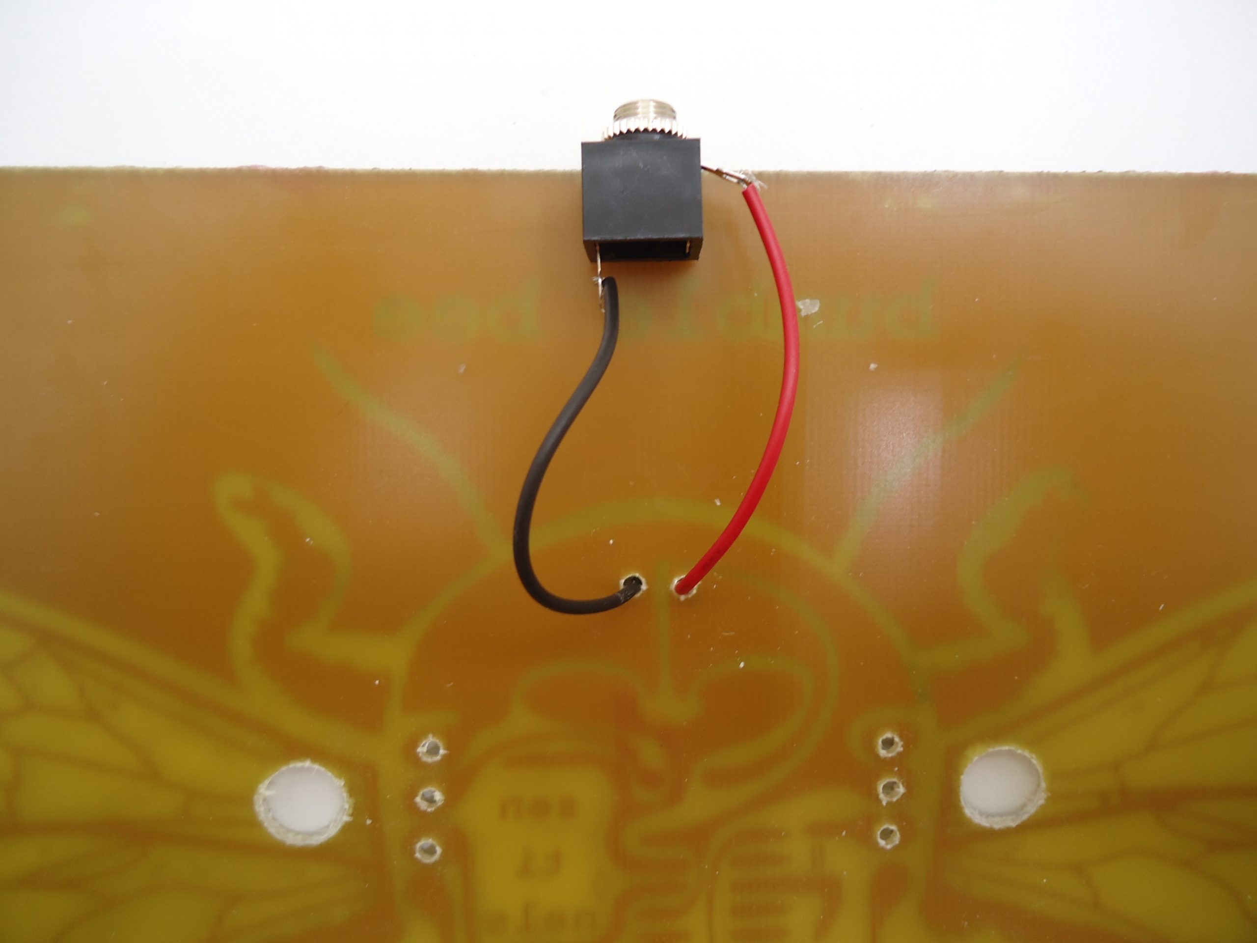
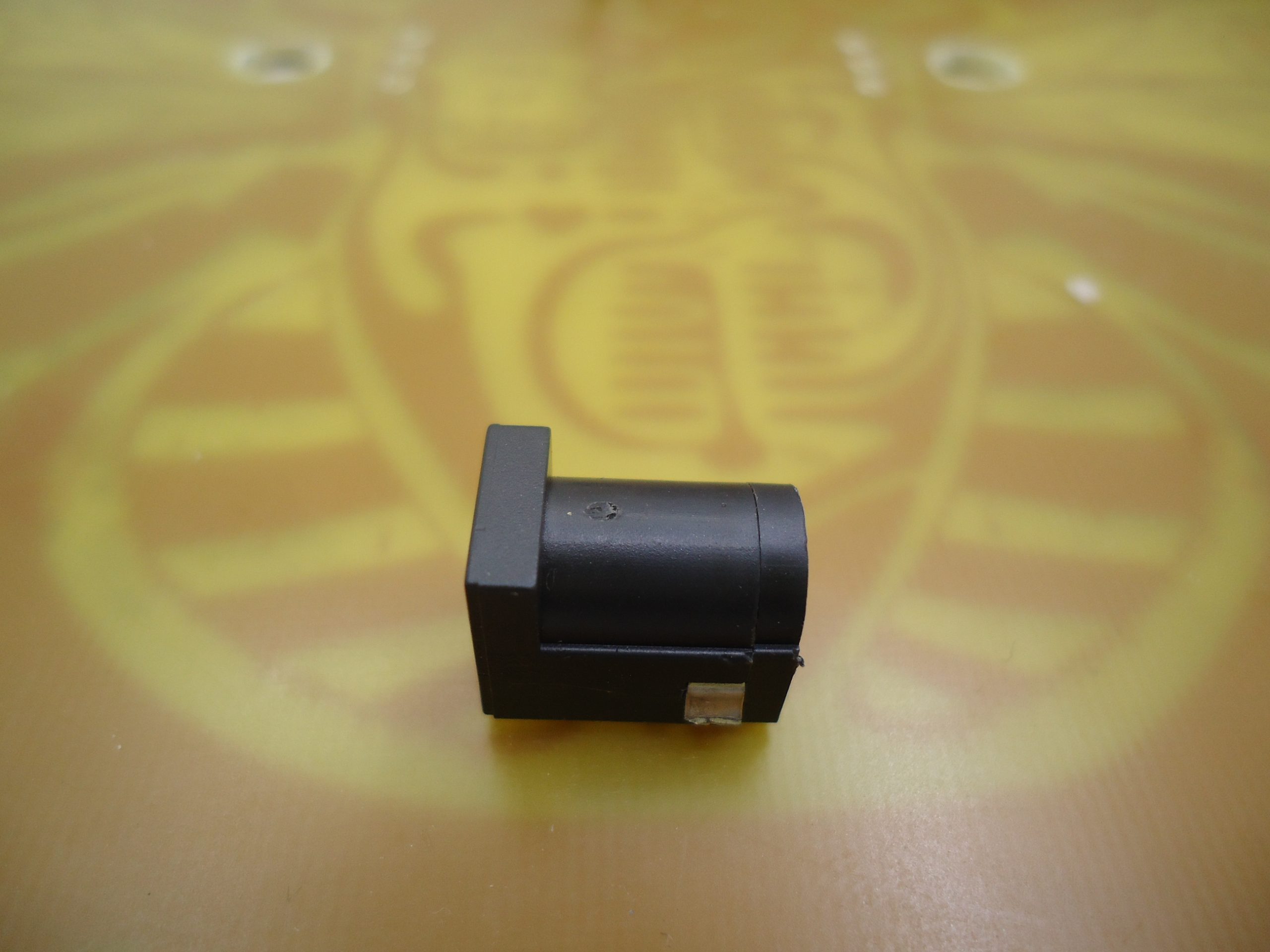
I recommend that you use an adapter, but if you do not have it, take the connector from the box and a 9V battery.

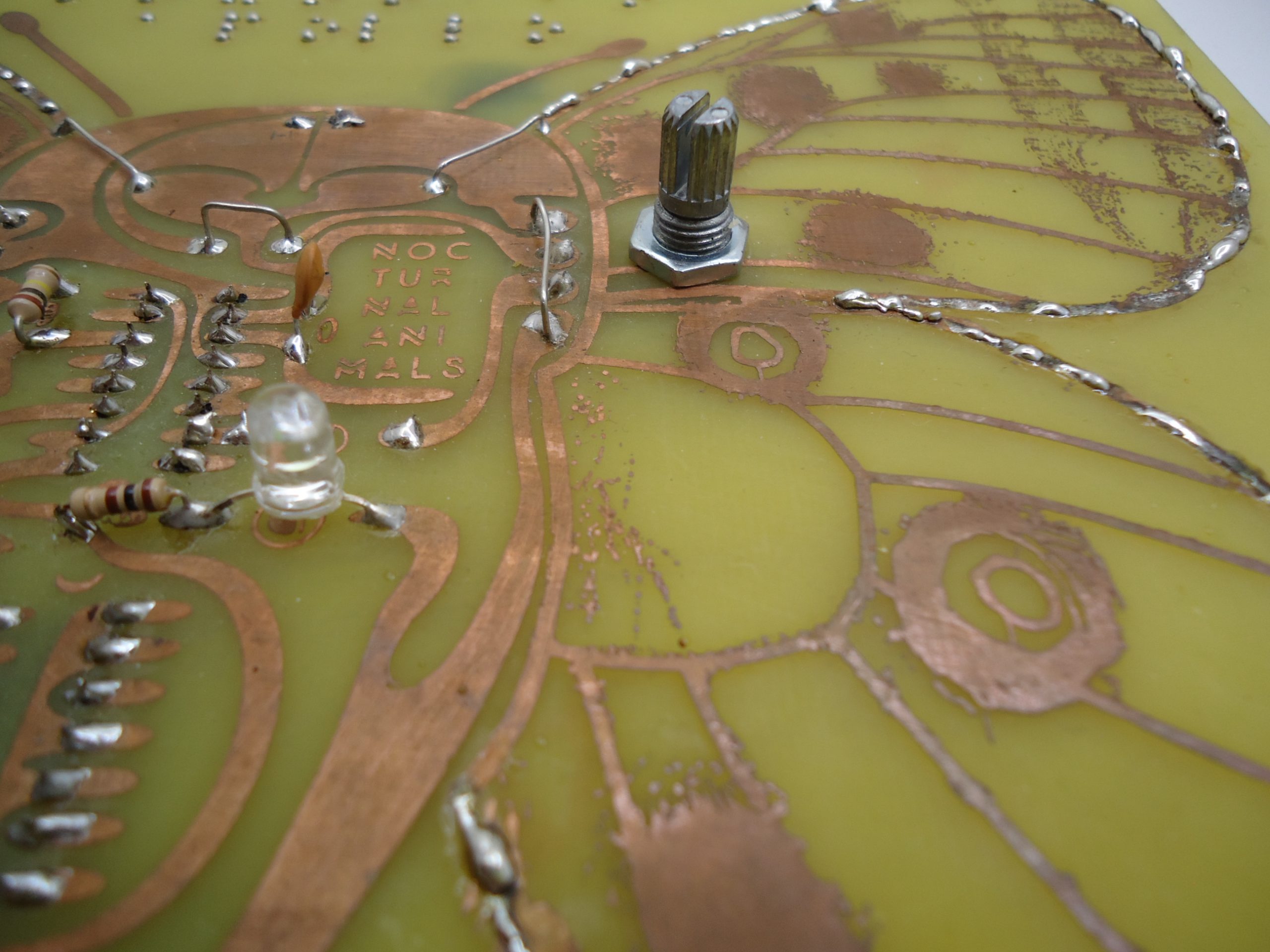
Sentinel is a really squeaky creature. The left potenciometer is the volume, the right one is the pitch. Touch the wings, hover your hand over the wings, solder one long wire somewhere on the wing and put the other end into a p

Troubleshooting
    • Make sure the orientation of all the components is correct [IC, C3, C4, J, PJ].
    • If the LED light does not light on, check:
      • If you turned the LED light is soldered in the right direction
      • If the power jack is soldered in the right direction
      • If the power jack is soldered enough to the connection on the board (the pins are quite big, therefore they need a little bit more solder).
    • If you know how to use the multimeter, check if all the connections are in order – they make a beep.
    • Check your solder joints [especially around the chips]. Maybe you were too generous with solder and some joints are soldered together.